ESTD. : 1958 : ISO CERTIFIED 9001 : NSIC REGISTERED
ESTD. : 1958 : ISO CERTIFIED 9001 : NSIC REGISTERED
Electronically Operated Synchronized Screw Jack
INTRODUCTION
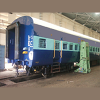
We are proud of being the leading manufacturers in India for more than three decades. These jacks have been specially developed by us to meet the requirements of various Railways & Commercial concerns. Our jack are better in shape, design & technology than the imported ones and are the most dependable, trouble-free in operation & needs minimum maintenance. It is worthwhile to maintain that their performance & low cost factor have posted a serious challenge to others.
The other names of this product 'Electronically Operated Synchronized Screw Jack', are Lifting Column , Electro Mechanical Jacks, Electric Jacks , Mobile Jacks, Portable Jacks , Loco Lifting Jacks , Coach Lifting Jacks etc.
The other names of this product 'Electronically Operated Synchronized Screw Jack', are Lifting Column , Electro Mechanical Jacks, Electric Jacks , Mobile Jacks, Portable Jacks , Loco Lifting Jacks , Coach Lifting Jacks etc.
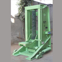
RIGIDITY & STABILITY
The jacks are of robust, rigid & of sturdy construction. They are suitably designed to meet heavy duty demands in various operations. The manufacturing process is supervised by the experienced technical experts & all sorts of precautions are taken to ensure safety & durability aspects. Each fabrication of critical load bearing assemblies is adequately strengthened.
MOBILITY
The jacks are provided with 3 retractable steel wheels of adequate strength and mounted in such a manner that when the claw carriage is moved upwards under load, the wheels will be automatically raised & the base of the jack sits firmly on the floor. Similarly, when the claw carriage is lowerd & the jack is released, the wheels will automatically be lowered to rest on floor so that the base is raised to provide the specified ground clearance.
JACK FRAME
The frame is fabricated from high quality steel conforming to IS : 226/2062. It is suitably webbed & strengthened with stiffners & securely welded to the heavy base. The base is of large area to prevent sinking of the jack into the shopfloor while lifting heavy loads. The base is heavy duty and is suitably strengthened to bear the heavy loads of Locomotives and rolling stock. The upright column is fully machined for smooth movement of the lifting claw.
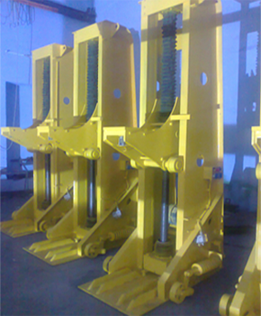
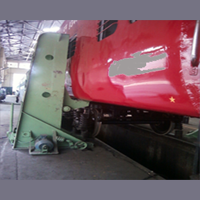
LIFTING CLAW CARRIAGE
The lifting claw carriage is of fabricated steel designed for lifting under the side of the vehicle & runs on the vertical carriage guides providede on frame. The carriage is mounted on suitable alloy steel rollers fitted with anti-friction bearings. The vertical downward load on the lifting claw is countered by a set of rollers mounted on the carriage against upward frame. The lifting claw is also provided with a chequered plate.
LOAD SCREW & NUT
The load screw & the nut, used in jacks are generously proportioned to withstand regular lifting of heavy loads. The screw of high quality steel having single start buttress thread in accordance with IS:4696. The screw is axially free at the bottom & splined to the warm wheel. The load is borne on a heavy duty ball thrust bearing having a spherical seated housing fixed at the top.
In our Jack the main load nut is of AL-Bronze, conforming to IS : 305 Grade AB-I. A safety steel nut is also provided as a safety device underneath the load nut to prevent any accidental fallng of load. The safety steel nut is controlled with two vertical guides which are fixed to the load nut. If the load nut wears to breaks then the safety nut immediately acts as a support & takes the load. This is a clear indication to replace the load nut, since the load is borne by the safety nut, the jacks would not operate.
In our Jack the main load nut is of AL-Bronze, conforming to IS : 305 Grade AB-I. A safety steel nut is also provided as a safety device underneath the load nut to prevent any accidental fallng of load. The safety steel nut is controlled with two vertical guides which are fixed to the load nut. If the load nut wears to breaks then the safety nut immediately acts as a support & takes the load. This is a clear indication to replace the load nut, since the load is borne by the safety nut, the jacks would not operate.
DRIVE MOTOR & TRANSMISSION
The jacks are driven by squirred cage motors, totally enclosed fan cooled, foot mounted, operating on 415 volts+-10%, 3 phase, 50 cycleA.C. supply. The power from motors is rransfered to a totally enclosed, oil-immersed reduction gear system, our own make. Each jack is provided with suitably made hand feiven manual handle to operate in case of power failure.
MOBILE CONTROL PANEL & ELECTRONIC SYSTEM
The control of the jacks is from master control panel. The jacks can be operated synchronously, either individually or in a group of four jacks. Suitable safety measures are provided for the synchronous operation of the jacks. Emergency push button stops are also provided on each jack as well as on control panel. All the jacks woukd stop instantly, if any of the jack fails, by prssing any of the emergency push buttons. The jacks will automatically go into locked position in case of power failure, failure of any component or faulty operation to ensure safety. When all the jacks are operating synchronously, all the jackswill stop immediately if any one jack fails, resulting in overloading of other jacks & the overload release will come into action. This eliminates any possiblitity of an accident due to the failure of one jack. Electrical limit switches are also provided on each jack at the extrimities of the lifting claw travel.
BASE
The base is of fabricated steel, incorporating a gear box for the warm and worm wheel which run in oil. All the mechanism for hand operation is carried on the base in portable type (H-type column) only.
MOBILITY
The wheels are mounted on antifriction bearings and are of large diameter, enabling the jacks to be moved easily on shop floor.
Leading Dimensions for Portable Jacks(Approximate)
LIFTING CAPACITY
TONNES
15
20
25
30
35
LIFTING CAPACITY
TONNES
15
20
25
30
35
Motror Rating
H.P.
5
7.5
7.5
10
12.5
Lifting Speed/Min.
MM
250
200
200
175
175
Max. height of claw from ground
MM
1755
1900
2085
2600
2600
Max. closed height of claw from ground
MM
600
600
625
800
800
Lifting Range
MM
1200
1400
1400
1600
1600
Max. foot projection from front of screw
MM
540
540
390
390
390
Max. claw rojection from front of screw
MM
450
450
300
300
300
Claw Load Plate Size
MM
200
200
210
210
210
Ground clearance when resting on wheels
MM
2500
2700
2700
2800
2800
Height of Jack
MM
2500
2700
2800
2800
2800
Length of Jack
MM
1450
1450
1300
1300
1350

